As a second tier Sub-Contractor under NGIS RTIC Modification Contract H94003‐04‐D‐0005.0030, ACL provided FAA licensed personnel for the initial Site Survey of C-130H 2.0-3.0 Block aircraft, and follow-on initial and ongoing installation design and integration phase modifications.
ACL provided the necessary FAA licensed Airframe & Powerplant technicians and supervisor for the initial 12 TVI installs (Test Vehicle Installations), and for follow-on LRIP installs (Low Rate Initial Production) at ANG/AFRC installations in Charleston, West Virginia, Youngstown, Ohio, Minneapolis, Minnesota, Schenectady, New York and Louisville, Kentucky.
ACL also participated in the Flight Test Program on the first two RTIC TVI’s working with Northrop Grumman Engineers at DMAFB, and performed Quality Control Inspections and necessary Field Modifications with Northrop Grumman staff.
ACL completed 24 of the C-130 RTIC modifications before its request to be contractually released from Borsight LLC.
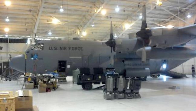
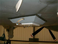
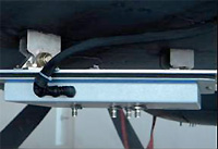
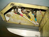
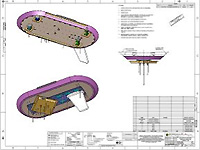
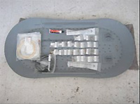
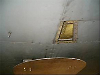
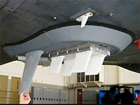
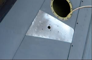
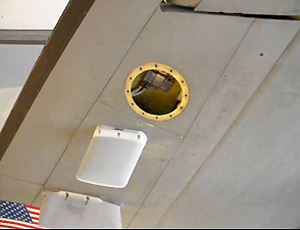
Pictured:
Typical C-130H-2.5, RTIC Mod Aircraft